Retrofitting Interior Insulation to a Pitched Roof

Retrofitting Interior Insulation to a Pitched RoofConverting attic space into living space becomes increasingly popular. Since the unvented type of insulation is energetically more favorable and since this type is easier to install if the insulation has to be added to an existing roof, it should be preferred over a vented variant, unless possible moisture problems are a concern. Since older pitched roofs usually have a relatively vapor-tight exterior lining (e.g. bituminous roofing felt on wood sheathing) they require an analysis of possible condensation problems. German standard DIN 4108-3 dispenses with calculational approval if the room-side vapor barrier has a very high vapor resistance (sd-value > 100 m). However, because such constructions which are then vapor-tight on both sides run a considerable risk of severe moisture damage if small defects or leaks occur, it is advisable not to follow the standard here as was already correctly pointed out in [1]. It has also been recommended there to use vapor retarders instead whose diffusion resistance has been selected to limit condensation in winter to an uncritical level while some drying of moisture that has infiltrated in the component is allowed in summer.

This is a typical optimization problem which clearly demonstrates the advantages of computational simulation. If the traditional Glaser method is used for this, a minimum sd-value of about 2 m is found. However, the Glaser method only approves the construction if the prescribed boundary conditions for roofs are used (surface temperature 20 °C). If the boundary conditions for walls are used, then the amount of condensing moisture usually exceeds the amount of evaporating moisture and the construction fails the Glaser test. Whether a high-pitched roof facing north can be assessed more realistically using the boundary conditions for flat roofs exposed to sunshine or boundary conditions for walls is left to the judgement of the person in charge. In the following it will be shown which insight can be gained with WUFI calculations.

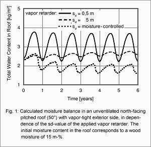
The effect of different boundary conditions and diffusion properties of the vapor retarder on the moisture situation in the north-facing half of an unvented double-pitch roof (inclination 50°) with vapor-tight exterior lining and insulation applied between the rafters has been investigated by computational simulation (see [2]). Fig 1 shows the evolution in time of the total moisture content in this roof for three different sd-values of the vapor retarder, assuming normal indoor moisture load, exterior climate conditions typical for Holzkirchen and an initial hygroscopic equilibrium moisture corresponding to 80% RH. If the vapor retarder has an sd-value of 0.5 m, the roof absorbs about 1.5 kg/m² of moisture from the indoor air in winter and completely releases it during the next summer, with the total water content at the end of the evaluation period of six years corresponding approximately to the initial water content. However, the high moisture accumulation in winter exceeds the limit for maximum condensation set by standard DIN 4108 and cannot be tolerated because the condensation moisture might collect and run off. If the sd-value of the vapor retarder is increased by a factor of ten, the moisture increase remains well below the critical limit of 0,5 kg/m². But now the moisture accumulates in the long term, as evidenced by the slow year-by-year increase of the computed moisture contents. A possible solution for this situation is a vapor retarder with variable sd-value, whose moisture-adaptive properties make it more vapor-tight in winter than in summer. Such a vapor retarder combines a low moisture increase by condensation in winter with a high drying potential in summer, so that the moisture content at the end of the evaluation period is even lower than in the other cases.

Specifications devised by extensive WUFI calculations were used to guide the development of this unique vapor retarder, providing another example for successful application of hygrothermal simulations to the development and optimization of building products [3].


Literature

Schulze, H.: Hausdächer in Holzbauart. Werner-Verlag, Düsseldorf 1987.
Künzel, H.M.: Bedeutung von Klimabedingungen und Diffusionseigenschaften für die Feuchtesicherheit voll gedämmter Altbaudächer. Festschrift zum 60. Geburtstag von Prof. Gertis. Fraunhofer IRB Verlag, Stuttgart 1998, S.371-389.
Künzel, H.M. und Kasper, F.-J.: Von der Idee einer feuchteadaptiven Dampfbremse bis zur Markteinführung. Bauphysik 20 (1998), H.6, S.257-260.


Page created: 10 May 2007; last update: 17 Jul 2012
Construction Moisture in a Cellular Concrete Flat Roof

onstruction Moisture in a Cellular Concrete Flat RoofThe drying of a cellular concrete flat roof is a classic example for the application of modern computational simulation methods. Since traditional methods considering only vapor diffusion were not sufficient to explain the drying behavior of these flat roofs, a new calculation method [1] was introduced in the early 80s which allowed for capillary transport, too, and was thus able to quantitatively reproduce experimental results obtained in the 60s [2]. Since this type of construction has recently attracted the attention of experts because of moisture problems during the drying phase in more southern climates, it will be used here as an example for investigating the hygrothermal behaviour of massive flat roofs.
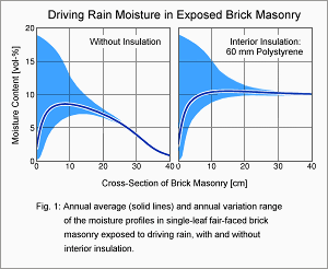
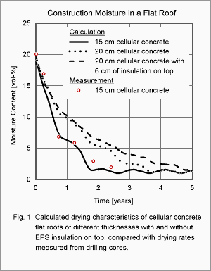
Fig. 1 shows the computed drying curves for three different flat roof variants, each starting with 20 vol-% of construction moisture in the prefabricated cellular concrete elements at the beginning of the first year. A comparison of the computation with measurements obtained for the 15 cm thick roof [2] shows the quality of the calculational prediction. The initial strong drying by 10 vol-% (15 kg/m²) within six months is due to strong heating of the bituminized roof surface by solar irradiation.

Since the roof can only dry towards the indoor side, a strong moisture load on the indoor air is created which must be removed promptly. While at temperate latitudes this is routinely achieved by simply opening the windows for an appropriate period of time, the air conditioning equipment used in hot and humid climate zones often cannot cope with the additional moisture so that indoor humidity may exceed permissible levels during the drying period of the roof.

The designed U-value of the roof is only reached when its moisture content falls below the reference moisture content of cellular concrete (about 1.5 vol-%). With the 15-cm-thick roof this happens within less than two years. A 20 cm thick cellular concrete roof already takes 3.5 years to dry out, which is roughly double the time. If 6 cm of polystyrene insulation are applied on top of the latter roof, its drying time reaches approximately five years. This example demonstrates the considerable influence of solar irradiation on the moisture behavior of flat roofs. While the additional insulation raises the overall temperature level of the cellular concrete, it also strongly suppresses the surface temperature peaks in summer. Since saturation vapor pressure rises exponentially with temperature, this reduction of peak temperatures slows the diffusion-dominated drying following the initial moisture loss which is supported by capillary forces.


Literature

Kießl, K.: Kapillarer und dampfförmiger Feuchtetransport in mehrschichtigen Bauteilen; rechnerische Erfassung und bauphysikalische Anwendung. Diss. Universität-Gesamthochschule Essen 1983.
Künzel, H.: Untersuchungen über die Feuchtigkeitsverhältnisse in Flachdachkonstruktionen. Berichte aus der Bauforschung H. 48, Verlag Ernst & Sohn, Berlin 1966


Page created: 09 May 2007; last update: 17 jul 2012

Driving Rain Moisture in Fair-faced Brickwork with Interior Insulation

Driving Rain Moisture in Fair-faced Brickwork with Interior InsulationFrom a hygrothermal point of view, an exterior insulation is in general preferable over an interior insulation. However, economical aspects or the wish to preserve historical facades may rule out exterior insulation, so that interior insulation remains the only way to reduce the energy consumption of a building and to increase comfort. The resulting risk of interstitial condensation and possible countermeasures (e.g. vapor barriers) are widely known.
It is less well known, however, that an interior insulation affects the moisture content of a facade exposed to rain and may increase the risk of frost damage. The influence of this effect on the moisture behaviour of a fair-faced solid-brick masonry wall exposed to driving rain has been investigated by computational simulation in [1] and has been verified by accompanying open-air experiments. Fig. 1 shows the moisture conditions in a 40-cm-thick masonry wall without and with interior insulation after periodic equilibrium has been reached (that is, the simulation is run for several years, always applying the same yearly weather data, until the transient moisture profiles repeat from one year to the next). The blue area shows the bandwidth of the moisture contents occuring during one year, plotted over the cross-section of the walls. The dark curve describes the yearly averages of the moisture contents for the region between the exterior surface of the wall and the point close to the interior surface where the interior rendering or the polystyrene foam insulation begins.

Despite recurring water saturation of the facade during periods of intense driving rain, the average moisture content at the exterior surface corresponds roughly to the reference moisture content of the masonry because sunshine quickly dries the surface. Due to the strong moisture-dependence of capillary transport, however, deeper below the surface the average moisture content increases quickly. In the wall without interior insulation, the moisture content reaches a maximum at a depth of a few centimeters and then decreases quite smoothly until it reaches the hygroscopic dry level on the indoor side. Beyond a depth of about 20 cm, the moisture content shows no variation over the whole year, that is, the transient outdoor climate only affects the exterior half of the masonry.

Applying an interior insulation changes the moisture conditions in the masonry drastically. Below the exterior surface, the moisture content now increases even stronger, without ever decreasing towards the indoor side. There are two reasons for this: while the driving rain load has not changed, the diffusion resistance of the polystyrene insulation slab impedes the drying through the indoor surface, and in addition the average temperature level of the masonry is reduced by the insulation, so that drying towards the exterior side is slowed down, too. In comparison with the uninsulated case the total moisture content in the insulated wall is noticeably increased. The risk of frost damage is increased accordingly and can only be reduced by improved rain protection such as hydrophobic facade treatments [1].

Literature

Künzel, H.M. und Kießl, K.: Feuchte- und Wärmeschutz von Sichtmauerwerk mit und ohne Fassadenhydrophobierung. Mauerwerksbau aktuell 98 (1998) S. D48-D57.


Page created: 09 May 2007; last update: 17 Jul 2012

Summer Condensation in Sandwich Construction

Summer Condensation in Sandwich ConstructionIn sandwich wall constructions the outer leaf provides the weathering protection. Even if there is no air gap between the outer leaf and the core insulation, capillary infiltration of rain water is limited to the outer leaf if hydrophobic insulation materials are used and the whole construction is windproof [1]. Thus, if the wall is properly executed, the construction layers behind the facework are durably protected from precipitation water.
In summer, however, moisture may be transported into these deeper layers by so-called reverse diffusion (also known as summer condensation). If the outer leaf is heated by sunshine, the rain water it contains will be carried across the core insulation by vapor diffusion and condense in the cooler inner leaf. If the inner leaf is masonry, the condensation moisture is harmlessly absorbed as capillary water in its pore spaces and given off in cooler periods. However, if the inner leaf contains materials which are susceptible to moisture damage, such as wood, summer condensation may create problems.

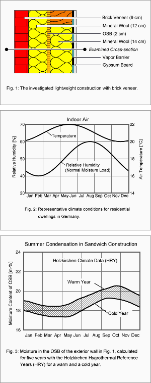
The effect of summer condensation occurring in the wall construction shown in Fig. 1 has been investigated by computational simulation. The inner leaf is a simple wooden post-and-beam structure. The outer leaf is clinker facework with a relatively low water absorption coefficient (A-value) of 1,0 kg/m²h½. The 12-cm-thick cavity between the facework and the OSB board covering the inner leaf is completely filled with hydrophobic mineral wool insulation. The investigation considers a typical cross-section of the west-facing wall during the fifth year of exposure to weather and focuses on the moisture content of the OSB board. The indoor climate used for the calculations is shown in Fig. 2, a cold and a warm year measured in Holzkirchen (HRY – Hygrothermal Reference Years) were used for the outdoor climate conditions.

Fig. 3 shows the spread of moisture conditions that occur in the OSB board, depending on the outdoor climate. In contrast to what is usually expected, the OSB board dries out during winter, starts to continuously accumulate moisture around May, reaches a maximum in autumn and then starts to dry again. As described above, the moisture accumulation during summer is due to reverse vapor diffusion. In a cold year, this does not create a critical situation for the wall construction investigated here. In a warm year, however, the moisture content in the OSB board exceeds 20 mass-%. Since relatively high temperatures occur at the same time, long-term damage caused by microorganisms can not be excluded.

This example is a striking demonstration of the fact that under certain circumstances warm weather can hold a higher risk than colder weather.

Literature

Künzel, H.: Zweischalige Außenwände mit Kerndämmung und Klinkerverblendung. wksb 37 (1996), S. 15-19.


Page created: 08 May 2007; last update: 17 Jul 2012

Construction Moisture in Exterior Wall with ETICS

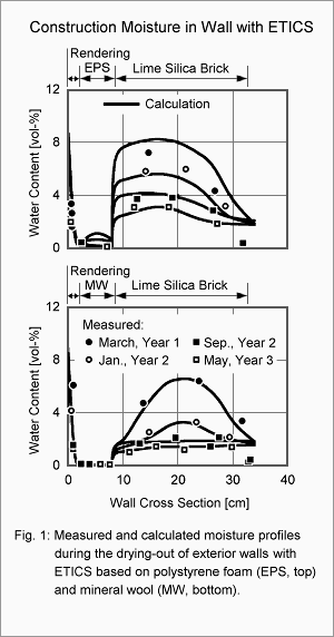
Construction Moisture in Exterior Wall with ETICSExternal Thermal Insulating Composite Systems (ETICS) provide both thermal and weathering protection for exterior walls. Therefore they are not only applied to new buildings but also successfully used for the rehabilitation of old buildings. In the latter case they also provide durable corrosion protection for the reinforcements in prefabricated slab constructions [1]. In all these cases, quick drying-out of the underlying construction is desirable in order to stop corrosion or moisture-induced heat loss. In the following, the drying-out of construction moisture in a 24 cm thick lime silica brick wall with an 80 mm thick ETICS containing mineral wool (MW) or polystyrene foam (EPS) insulation will be investigated by calculation and experiment, and conclusions based on further calculations will be presented.

For details on wall construction, material properties and how the outdoor tests and WUFI calculations were performed, please refer to [2]. Fig. 1 shows a comparison of the computed and measured moisture distributions for various points in time after completion of the test house (the measurements were done on drill cores). For both the wall with EPS insulation and the wall with MW insulation good agreement between computed and measured results is achieved.

The shapes of the moisture profiles show that in the wall with EPS insulation most of the moisture is drying toward the interior, while the mineral wool also allows noticeable drying of the masonry toward the exterior. It takes the wall with mineral wool insulation about a year and a half to reach hygroscopic equilibrium, and about twice that time for the EPS insulation. During the drying phase, the heat losses caused by increased thermal transmission and by the increased ventilation necessary for removing the construction moisture are not negligible. In the case of the lime silica brick masonry with its low insulation quality the moisture level during the first year increases the U-value by about 5%. With masonry of aerated honeycomb bricks under the ETICS, the U-value would be increased by about 25%, as shown by computations in [3].

Since the designed U-value is reached only at the end of the drying period, quickly drying wall constructions help to save heating energy. Constructions which are vapor-permeable on both sides and thus can dry equally to the interior and the exterior side are particularly favorable. On the other hand, in walls with vapor-retarding covering on both sides, e.g. with an EPS insulation on the outside and tiles on the inside, it may take the construction moisture more than five years to dry out completely.

Literature

Cziesielski, E.: Energiegerechte Sanierung von Korrosionsschäden bei Stahlbetongebäuden. Bauphysik 13 (1991), H.5, S.138-143.
Künzel, H.M.: Austrocknung von Wandkonstruktionen mit Wärmedämm-Verbundsystemen. Bauphysik 20 (1998), H.1, S.18-23.
Holm, A. und Künzel, H.M.: Trocknung von Mauerwerk mit Wärmedämmverbundsystemen und Einfluß auf den Wärmedurchgang. Tagungsband 10. Bauklimatisches Symposium, Dresden 1999, S.549-558


Page created: 07 May 2007; last update: 17 Jul 2012

Perimeter Insulation Exposed to Ground Water

Perimeter Insulation Exposed to Ground WaterUnder Central European climate conditions a perimeter insulation usually presents no hygric problems. However, this does not apply to insulation exposed to ground water. In this case only closed-cell insulation materials such as foam glass or extruded polystyrene rigid foam (XPS) are admissible.

Since XPS – as opposed to foam glass – is not completely impermeable to water vapor, care must be taken to prevent water from ever seeping behind the insulation slabs. This can only be ensured by installing the insulation with durable full-face bonding between cellar wall and insulation slabs. Unfortunately, practical experience shows that this is not always done carefully enough and that moisture can then penetrate into areas with no or with incomplete bonding. From the warm side of the insulation slab, vapor diffusion will then transport moisture into the cooler parts of the insulation material. This leads to moisture accumulation in the insulation slabs around these defects and thus degrades the thermal insulation of the cellar.

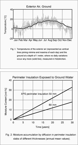
In [1] the moisture behavior of an XPS perimeter insulation applied to walls of a heated cellar has been simulated, assuming that ground water has penetrated behind the insulation slabs. Under the ground temperature conditions shown in Fig. 1 diffusion of the ground water that has seeped behind the warm side of the insulation leads to continuous moisture accumulation in the insulation slabs (Fig. 2).

As opposed to measurements on sporadically taken samples, the simulation allows to extrapolate the moisture conditions over a longer period of time. The long-term moisture accumulation is much more pronounced in a perimeter insulation with only 50 mm thickness than in one with 80 mm thickness. The smaller temperature gradient in the thicker insulation layer gives rise to a smaller vapor pressure gradient on the warm side, which leads to less accumulated moisture because of the reduced vapor diffusion flow. In both cases, in the area around the defect the U-value of the insulated cellar wall increases markedly over the course of 30 years (by about 70% in the 80-mm-insulation and by about 140% in the 50-mm-insulation). Such a degradation of the insulation quality is not acceptable. It is therefore important to exercise great care when applying XPS perimeter insulation slabs exposed to groundwater.

Literature

Künzel, H.M.: Feuchteaufnahme von Perimeterdämmplatten aus extrudiertem Polystyrol-Hartschaum im Grundwasserbereich bei nicht vollflächiger Verklebung. IBP-Bericht FtB-38/1995.


Page created: 27 Apr 2007; last update: 17 Jul 2012

Product Development with the Help of Hygrothermal Simulations

DampfbremseProduct development is often a continuous process in which existing materials and/or components undergo incremental improvements over potentially long periods of time. The optimization of bricks and mortar to improve the thermal resistance of monolithic walls is one example of continuous product development.

The development of entirely new materials usually begins with an idea that will address a practical problem. The next stage of the development usually draws on existing experience and knowledge, but the success and speed of the development will depend on a number of factors. For new building materials and components, hygrothermal simulations can aid in the development process.

This document will describe the development of “smart,” humidity-controlled vapor retarders. Since their market launch in 1997, smart vapor retarders are now well established in the building industry. The development of smart vapor retarders was aided by hygrothermal simulations.

Contine reading