 Converting attic space into living space becomes increasingly popular. Since the unvented type of insulation is energetically more favorable and since this type is easier to install if the insulation has to be added to an existing roof, it should be preferred over a vented variant, unless possible moisture problems are a concern. Since older pitched roofs usually have a relatively vapor-tight exterior lining (e.g. bituminous roofing felt on wood sheathing) they require an analysis of possible condensation problems. German standard DIN 4108-3 dispenses with calculational approval if the room-side vapor barrier has a very high vapor resistance (sd-value > 100 m). However, because such constructions which are then vapor-tight on both sides run a considerable risk of severe moisture damage if small defects or leaks occur, it is advisable not to follow the standard here as was already correctly pointed out in [1]. It has also been recommended there to use vapor retarders instead whose diffusion resistance has been selected to limit condensation in winter to an uncritical level while some drying of moisture that has infiltrated in the component is allowed in summer.
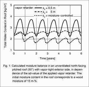
This is a typical optimization problem which clearly demonstrates the advantages of computational simulation. If the traditional Glaser method is used for this, a minimum sd-value of about 2 m is found. However, the Glaser method only approves the construction if the prescribed boundary conditions for roofs are used (surface temperature 20 °C). If the boundary conditions for walls are used, then the amount of condensing moisture usually exceeds the amount of evaporating moisture and the construction fails the Glaser test. Whether a high-pitched roof facing north can be assessed more realistically using the boundary conditions for flat roofs exposed to sunshine or boundary conditions for walls is left to the judgement of the person in charge. In the following it will be shown which insight can be gained with WUFI calculations.
The effect of different boundary conditions and diffusion properties of the vapor retarder on the moisture situation in the north-facing half of an unvented double-pitch roof (inclination 50°) with vapor-tight exterior lining and insulation applied between the rafters has been investigated by computational simulation (see [2]). Fig 1 shows the evolution in time of the total moisture content in this roof for three different sd-values of the vapor retarder, assuming normal indoor moisture load, exterior climate conditions typical for Holzkirchen and an initial hygroscopic equilibrium moisture corresponding to 80% RH. If the vapor retarder has an sd-value of 0.5 m, the roof absorbs about 1.5 kg/m² of moisture from the indoor air in winter and completely releases it during the next summer, with the total water content at the end of the evaluation period of six years corresponding approximately to the initial water content. However, the high moisture accumulation in winter exceeds the limit for maximum condensation set by standard DIN 4108 and cannot be tolerated because the condensation moisture might collect and run off. If the sd-value of the vapor retarder is increased by a factor of ten, the moisture increase remains well below the critical limit of 0,5 kg/m². But now the moisture accumulates in the long term, as evidenced by the slow year-by-year increase of the computed moisture contents. A possible solution for this situation is a vapor retarder with variable sd-value, whose moisture-adaptive properties make it more vapor-tight in winter than in summer. Such a vapor retarder combines a low moisture increase by condensation in winter with a high drying potential in summer, so that the moisture content at the end of the evaluation period is even lower than in the other cases.
Specifications devised by extensive WUFI calculations were used to guide the development of this unique vapor retarder, providing another example for successful application of hygrothermal simulations to the development and optimization of building products [3].
Literature
Schulze, H.: Hausdächer in Holzbauart. Werner-Verlag, Düsseldorf 1987.
Künzel, H.M.: Bedeutung von Klimabedingungen und Diffusionseigenschaften für die Feuchtesicherheit voll gedämmter Altbaudächer. Festschrift zum 60. Geburtstag von Prof. Gertis. Fraunhofer IRB Verlag, Stuttgart 1998, S.371-389.
Künzel, H.M. und Kasper, F.-J.: Von der Idee einer feuchteadaptiven Dampfbremse bis zur Markteinführung. Bauphysik 20 (1998), H.6, S.257-260.
Page created: 10 May 2007; last update: 17 Jul 2012
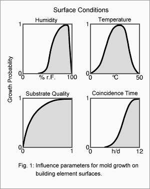 Under unfavorable ambient conditions, microbial growth may occur on the surfaces of building components. The most important factors are temperature, relative humidity, a substrate with sufficient nutrients and the daily duration of the period where all growth conditions prevail simultaneously (coincidence time). While bacteria need relative humidities of at least 90% for being able to grow, certain xerophilic fungi can thrive at humidities as low as 65%, and most fungi can cope with humidities as low as 80%. Mold fungi also tolerate a larger temperature bandwidth than other organisms, they may grow between 0°C and 50°C. Therefore the whole range of humidities and temperatures mentioned above may be considered to pose a potential mold growth risk.
 Converting attic space into living space becomes increasingly popular. Since the unvented type of insulation is energetically more favorable and since this type is easier to install if the insulation has to be added to an existing roof, it should be preferred over a vented variant, unless possible moisture problems are a concern. Since older pitched roofs usually have a relatively vapor-tight exterior lining (e.g. bituminous roofing felt on wood sheathing) they require an analysis of possible condensation problems. German standard DIN 4108-3 dispenses with calculational approval if the room-side vapor barrier has a very high vapor resistance (sd-value > 100 m). However, because such constructions which are then vapor-tight on both sides run a considerable risk of severe moisture damage if small defects or leaks occur, it is advisable not to follow the standard here as was already correctly pointed out in [1]. It has also been recommended there to use vapor retarders instead whose diffusion resistance has been selected to limit condensation in winter to an uncritical level while some drying of moisture that has infiltrated in the component is allowed in summer.
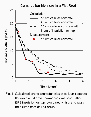 The drying of a cellular concrete flat roof is a classic example for the application of modern computational simulation methods. Since traditional methods considering only vapor diffusion were not sufficient to explain the drying behavior of these flat roofs, a new calculation method [1] was introduced in the early 80s which allowed for capillary transport, too, and was thus able to quantitatively reproduce experimental results obtained in the 60s [2]. Since this type of construction has recently attracted the attention of experts because of moisture problems during the drying phase in more southern climates, it will be used here as an example for investigating the hygrothermal behaviour of massive flat roofs.
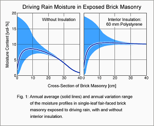 From a hygrothermal point of view, an exterior insulation is in general preferable over an interior insulation. However, economical aspects or the wish to preserve historical facades may rule out exterior insulation, so that interior insulation remains the only way to reduce the energy consumption of a building and to increase comfort. The resulting risk of interstitial condensation and possible countermeasures (e.g. vapor barriers) are widely known.
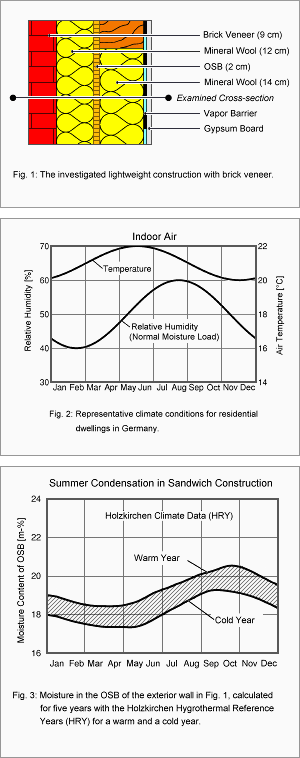 In sandwich wall constructions the outer leaf provides the weathering protection. Even if there is no air gap between the outer leaf and the core insulation, capillary infiltration of rain water is limited to the outer leaf if hydrophobic insulation materials are used and the whole construction is windproof [1]. Thus, if the wall is properly executed, the construction layers behind the facework are durably protected from precipitation water.
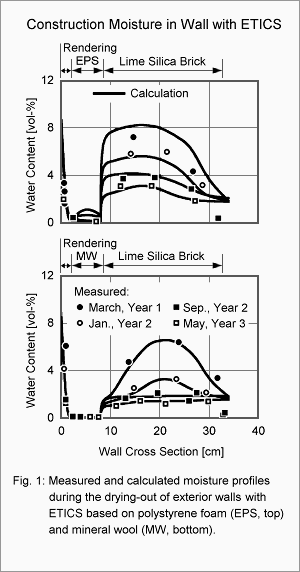
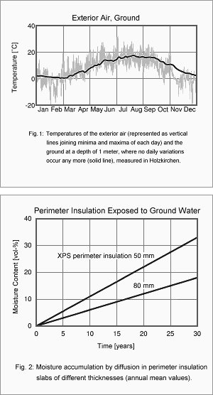 Under Central European climate conditions a perimeter insulation usually presents no hygric problems. However, this does not apply to insulation exposed to ground water. In this case only closed-cell insulation materials such as foam glass or extruded polystyrene rigid foam (XPS) are admissible.
 Product development is often a continuous process in which existing materials and/or components undergo incremental improvements over potentially long periods of time. The optimization of bricks and mortar to improve the thermal resistance of monolithic walls is one example of continuous product development.